Cart is empty
WAGO 789-665
789-665 WAGO 789-665
OutOfStock

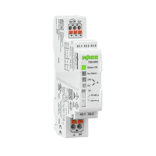
Ground resistance signaling module Ground fault alarm via digital output DC 24V
Got questions?
Send us a message
or call us at 1-800-335-5111 for additional assistance.
Ground resistance signaling module Ground fault alarm via digital output DC 24V
Features
- The module establishes an internal connection between the 0 V (X2.2) and ground (X2.1) connections via a semiconductor switch.
- At 10 s intervals, the connection between 0 V and ground is interrupted for 0.5 s, and the isolation resistance between +24 V (X1.3) or 0 V (X2.2) of the supply voltage and earth (X2.1) is determined.
- The grounding connection on the module does not meet the requirements of a protective earth terminal (PE). It serves as a functional ground. The measurement method does not involve the module establishing any permanent connection bet-ween 0 V and ground.
- In this operating mode, the semiconductor switch to establish a connection between 0 V (X2.2) and ground (X2.1) is deactivated. At 1 s intervals, the isolation resistance offset is determined for 0.5 s.
- The module does not meet the requirements of an isolation monitoring device per EN 61557-8.
- The potential-free contact serves the purpose of supporting evaluation (e.g., via a PLC) of looming isolation faults.
- This contact must not be used to switch safety-related products that could cause the circuit to switch off.
Approvals
- Underwriters Laboratories Inc., UL, E175199, UL 61010-2-201
- Underwriters Laboratories Inc., UL, E198726, UL 121201
Specifications
Supply
- Nominal supply voltage US: DC 24 V (SELV)
- Supply voltage range (DC): DC 18 … 31.2 V
- Power consumption at nominal supply voltage: ≤ 40 mA
- Power loss Pl: ≤ 1.7 W
- Current at ground fault (24 VDC) (max.): 56 mA
Signaling
- Operation status indicator: 1 x LED “Status OK” (green)
- Signaling: 1 x LED “Iso Alarm” (red) || 1 x LED “Iso Alarm” 24 V ‒ Ground (yellow) || 1 x LED “Iso Alarm” 0 V ‒ Ground (yellow) || 1 x Signal output “Iso OK”
Iso Ok Contact
- Schaltspannung max.: 48 VDC (SELV)
- Continuous current (max.): 500 mA (for general use)
- Number of Iso OK contacts connected in series (max.): 25 (Limit value type: 1); 32 (Limit value type: 2 and 3) (per IEC 61131)
- Function: 1 make contact (NO); closed with applied power supply and insulation resistance > limit value
Fuse Protection
- Required backup fusing: The fuse must be placed in the output circuit of the power supply. The fuse must be adapted to the power supply used and must trip safely in case of a short circuit. The module is designed for use with a 10 A (max. ) fuse or with a 10 ADC (max.) circuit breaker (characteristic B or C).
Safety And Protection:
- Pollution degree: 2
- Overvoltage category: II
- Protection type: IP20
- Test voltage (supply/"Iso OK" contact): 1.5 kVAC; 50 … 60 Hz; 1 min
- MTBF: > 600,000 h (per MIL-HDBK-217F2)
Mode: Ungrounded Control Circuit
- Response value for alarm at nominal supply voltage: 4 kΩ (at US = 24 V, for other values of US see signaling threshold characteristic)
- Response time: 1 s
- Hysteresis (typ.): 1 kΩ
Mode: Grounded Control Circuit
- Response value for alarm at nominal supply voltage: 4 kΩ (at US = 24 V, for other values of US see signaling threshold characteristic)
- Response time: 10 s
- Hysteresis (typ.): 1 kΩ
Environmental Requirements
- Surrounding air temperature (operation): -40 … +70 °C
- Surrounding air temperature (storage): -40 … +85 °C
- Temperature range of the connecting cable according to EN 61010-2-201: ≥ (Tsurrounding air + 10 K)
- Relative humidity: 5 … 95 % (non-condensing)
- Operating altitude (max.): 3000 m
Connection Data
- Connection type (1): X1.x
- Connection technology: Push-in CAGE CLAMP®
- WAGO Connector: picoMAX® eCOM
- Solid conductor: 0.25 … 1.5 mm² / 24 … 14 AWG
- Fine-stranded conductor: 0.25 … 1.5 mm² / 24 … 14 AWG
- Fine-stranded conductor; with insulated ferrule: 0.25 … 0.75 mm²
- Fine-stranded conductor; with uninsulated ferrule: 0.25 … 1.5 mm²
- Strip length: 8 … 9 mm / 0.31 … 0.35 inch
- Connection type 2: X2.x
- Connection technology 2: Push-in CAGE CLAMP®
- WAGO Connector 2: picoMAX® eCOM
- Solid conductor 2: 0.2 … 2.5 mm² / 24 … 12 AWG
- Fine-stranded conductor 2: 0.2 … 2.5 mm² / 24 … 14 AWG
- Fine-stranded conductor; with insulated ferrule 2: 0.25 … 1.5 mm²
- Fine-stranded conductor; with uninsulated ferrule 2: 0.25 … 2.5 mm²
- Strip length 2: 9 … 10 mm / 0.35 … 0.39 inch
Geometrical Data
- Width: 18 mm / 0.71 inch
- Height: 90 mm / 3.54 inch
- Depth from upper edge of DIN-rail: 51 mm / 2.01 inch
Mechanical Data
- Mounting type: DIN-35 rail
Material Data
- Fire load: 0.000 MJ
- Weight: 47.000 g
Standards And Specifications
- Conformity marking: CE
- EMC immunity to interference: EN 61000-6-2
- EMC emission of interference: EN 61000-6-3; EN 61000-6-4
- Standards/Specifications: UL 61010-2-201
Commercial Data
- Country of origin Sales Organisation Germany: CN
- GTIN: 4055144067200
- Customs tariff number Sales Organisation Germany: 85365005000


