Cart is empty
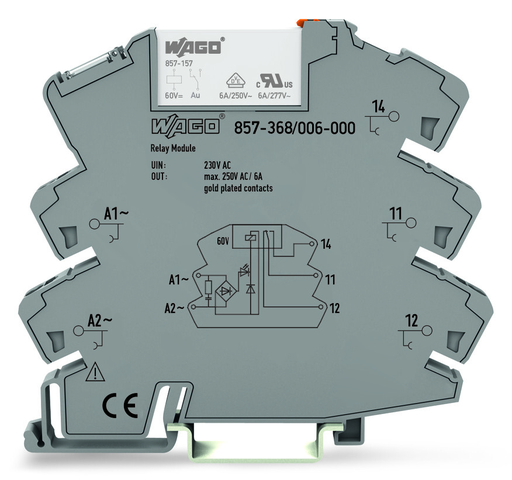
WAGO 857-368/006-000
857-368/006-000 WAGO 857-368/006-000
OutOfStock

Socket with miniature switch. rel.
Got questions?
Send us a message
or call us at 1-800-335-5111 for additional assistance.
Socket with miniature switch. rel.
Specifications
Notes
- Note: To prevent damaging the gold layer, 30 V switching voltages and 50 mA currents must not be exceeded. Higher switching power eventually evaporates the gold layer. The resulting deposits in the housing may reduce service life.To protect the relay coils and contacts, inductive loads must be dampened with an effective protection circuit.
Control Circuit
- Nominal input voltage UN: AC 230 V
- Input voltage range: -15 … +10 %
- Nominal input current at UN: 16 mA
- Line capacitance (max.): 170 nF
- Cable length (control circuit): ≤ 350 m (for a line capacitance of 330 nF/km)
Load Circuit
- Number of changeover/switchover contacts: 1
- Contact material (relay): AgNi + Au
- Limiting continuous current: 6 A
- Inrush current (resistive) (max.): (AC) 20 A / 0.02 s
- Switching voltage (max.): AC 250 V
- Switching power (resistive) (max.): AC 1500 VA; DC (see load limit curve)
- Switching capacity: AC-15: 3 A / AC 250 V; DC-13: 2 A / DC 24 V
- Recommended minimum load: 1 V / 1 mA / 1 mW
- Pull-in time (typ.): 15 ms
- Drop-out time (typ.): 25 ms
- Bounce time (typ.): 3.5 ms
- Electrical life (NO; resistive load; 23 °C): 50 x 103 switching operations
- Mechanical life: 5 x 10⁶ switching operations
- Switching frequency with/without load (max.): 6 min-1 / 180 min-1
Signaling
- Status indicator: Yellow LED
Safety And Protection
- Rated voltage: 300 V
- Rated surge voltage: 4 kV
- Circuit type: Mains circuits
- Overvoltage category: III
- Pollution degree: 2
- Dielectric strength, control/load circuit (AC, 1 min): 3.51 kVrms
- Dielectric strength, open contact (AC, 1 min): 1 kVrms
- Insulation type (control/load circuit): Reinforced insulation (safe isolation)
- Insulation type (between adjacent devices of the the same type): Reinforced insulation (safe isolation)
- Protection type: IP20
Connection Data
- Connection technology: Push-in CAGE CLAMP®
- Solid conductor: 0.34 … 2.5 mm² / 22 … 14 AWG
- Fine-stranded conductor: 0.34 … 2.5 mm² / 22 … 14 AWG
- Strip length: 9 … 10 mm / 0.35 … 0.39 inch
Physical Data
- Width: 6 mm / 0.236 inch
- Height: 94 mm / 3.701 inch
- Depth from upper edge of DIN-rail: 81 mm / 3.189 inch
Mechanical Data
- Mounting type: DIN-35 rail
Material Data
- Color: Gray
- Fire load: 0.000 MJ
- Weight: 31.477 g
Environmental Requirements
- Surrounding air temperature (operation at UN): -40 … 60 °C
- Surrounding air temperature (storage): -40 … 70 °C
- Processing temperature: -25 … +50 °C
- Relative humidity: 5 … 85 % (no condensation permissible)
- Operating altitude (max.): 2000 m
Standards And Specifications
- Standards/Specifications: EN 61010-2-201 || EN 61810-1 || EN 61373
Basic Relay
- WAGO Basic Relay: 857-157
Commercial Data
- Packaging type: Box
- Country of origin Sales Organisation Germany: DE
- GTIN: 4050821873402
- Customs tariff number Sales Organisation Germany: 85364900990


