Cart is empty
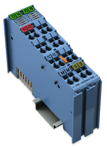
WAGO 750-487/003-000
750-487/003-000 WAGO 750-487/003-000
OutOfStock

2CH AI THERMO EXI
Got questions?
Send us a message
or call us at 1-800-335-5111 for additional assistance.
2-Channel analog input module for thermo-elements Ex i
Features
- Indicators:Green LED (availability ON/OFF)
- Red LED (wire breakage, measurement range overflow/underflow)
Approvals
- UL International Netherlands B.V., UL, E175199 Sec.1, UL 508
- TUEV Nord Cert GmbH, IECEx, IECEx TUN 09.0001 X, IEC 60079-0
- RINA Germany GmbH, RINA, ELE066419XG
- Lloyds Register EMEA, LR, 02/20026 (E6)
- Underwriters Laboratories Inc., UL, E198726 Sec.1, UL 121201
- Nippon Kaiji Kyokai, NK, TA17255M
- Det Norske Veritas, Germanischer Lloyd, DNV GL, TAA0000194
- American Bureau of Shipping, ABS, 19-HG1821926
- TUEV Nord Cert GmbH, TUEV Nord, IECEx TUN 12.0039X, IEC 60079
- UL International Germany GmbH, AEx, E480271, UL 60079
- National Radio Research Agency, KC, MSIP-REM-W43-AIM750, Article 58-2, Clause 3
- CQST/CNEx, CCCEx, 2020312310000211, CNCA-C23-01
- Bureau Veritas S.A., BV, 30389/B0 BV
- TUEV Nord Cert GmbH, ATEX, TUEV_12_ATEX_106032X, EN 60079-0
- TÜV Rheinland do Brasil Ltda., INMETRO, TÜV_14.1911_X
- Polski Rejestr Statków, PRS, TE/2236/880590/19
Specifications
Notes
- Note: The analog output module must only be operated via 24 VDC Ex i!General information (e.g., installation regulations) on explosion protection is available in the WAGO I/O System 750 manuals!
Technical Data
- Number of analog inputs: 2
- Total number of channels (module): 2
- Signal type: Thermocouple || Low voltages
- Signal type (configurable): Yes
- Sensor connection: 2 x (2-wire)
- Power consumption Pmax.: 0.3 W
- Data width: 2 x 16-bit data; 2 x 8-bit control/status (optional)
- Internal resistance: 1000 kΩ
- Resolution (over entire range): 0.1 °C or 0.01 mV for voltage measurement
- Conversion time (typ.): 320 ms
- Conversion time: ≤ 320 ms (both channels)
- Measurement error (25 °C): < ±6 K (voltage input < ±2 K; cold junction compensation < ±4 K)
- Temperature coefficient: < ± 0.2 K / K of the largest output area (type K)
- Intrinsic safety Ex i: Yes
- Sensor types: Thermocouple K; Configurable: J, B, E, L, N, R, S, T, U, C; Voltage sensor: ±30 mV, ±60 mV, ±120 mV
- Temperature range: Type-dependent from –100 to +1.800 °C
- Measurement range: Thermocouples: Type B: +600 … +1.800 °C; Type E: –100 … +1.000 °C; Type J: –100 … +1.200 °C; Type K: –100 … +1.370 °C* *(default setting); Type L: -100 … +900 °C; Type N: –100 … +1.300 °C; Type R: 0 … +1.700 °C; Type S: –50 … +1.700 °C; Type T: –100 … +400 °C; Type U: -25 … +600 °C; Voltage sensors: MB1: ±30 mV; MB2: ±60 mV; MB3: ±120 mV
- Cold junction compensation: Internal; at each pair of terminal blocks
- Supply voltage (system): 5 VDC; via data contacts
- Power consumption (5 V system supply): 13.5 mA
- Supply voltage (field): 24 VDC; (Ex i power supply: UO = max. 27.3 V); via power jumper contacts (power supply via blade contact; transmission via spring contact)
- Power consumption, field supply (module with no external load): 8.5 mA
- Power loss Pl: 0.3 W
- Isolation: 300 VAC system/field
- Number of incoming power jumper contacts: 2
- Number of outgoing power jumper contacts: 2
- Marking: ATEX, IECEx, INMETRO, Underwriters Laboratories Inc.
Explosion Protection
- Ex guideline: EN IEC 60079-0, -7, -11
- Safety-relevant data (circuit): Uo = 14.4 V; Io = 29.1 mA; Po = 52.4 mW; Linear characteristic curve
- Reactances Ex ia IIC: Lo = 52 mH; Co = 650 nF
- Reactances Ex ia IIB: Lo = 100 mH; Co = 4.0 µF
- Reactances Ex ia IIA: Lo = 300 mH; Co = 15.8 μF
- Reactances Ex ia I: Lo = 400 mH; Co = 17.9 µF
- Reactances (note): Reactances without accounting for the concurrence of L and C
Connection Data
- Connection technology: inputs/outputs: 16 x CAGE CLAMP®
- Connection type (1): Inputs/outputs
- Solid conductor: 0.08 … 2.5 mm² / 28 … 14 AWG
- Fine-stranded conductor: 0.08 … 2.5 mm² / 28 … 14 AWG
- Strip length: 8 … 9 mm / 0.31 … 0.35 inch
Physical Data
- Width: 24 mm / 0.945 inch
- Height: 100 mm / 3.937 inch
- Depth: 67.8 mm / 2.669 inch
- Depth from upper edge of DIN-rail: 60.6 mm / 2.386 inch
Mechanical Data
- Mounting type: DIN-35 rail
Material Data
- Color: Blue
- Housing material: Polycarbonate; polyamide 6.6
- Fire load: 1.675 MJ
- Weight: 90.500 g
- Conformity marking: CE
Environmental Requirements
- Surrounding air temperature (operation): 0 … 55 °C
- Surrounding air temperature (storage): -40 … 85 °C
- Protection type: IP20
- Pollution degree (5): 2 per IEC 61131-2
- Operating altitude: 0 … 2000 m
- Mounting position: Horizontal (standing/lying); vertical
- Relative humidity (without condensation): 95 %
- Vibration resistance: 4g per IEC 60068-2-6
- Shock resistance: 15g per IEC 60068-2-27
- EMC immunity to interference: Per EN 61000-6-2, marine applications
- EMC emission of interference: Per EN 61000-6-3, marine applications
- Exposure to pollutants: Per IEC 60068-2-42 and IEC 60068-2-43
- Permissible H2S contaminant concentration at a relative humidity 75 %: 10 ppm
- Permissible SO2 contaminant concentration at a relative humidity 75 %: 25 ppm
Commercial Data
- Packaging type: Box
- Country of origin Sales Organisation Germany: DE
- GTIN: 4045454961893
- Customs tariff number Sales Organisation Germany: 85389099990


