Cart is empty
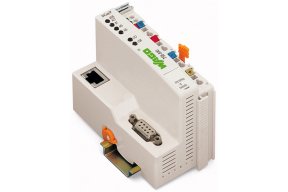
WAGO 750-830
750-830 WAGO 750-830
OutOfStock

BACnet/IP Controller
Got questions?
Send us a message
or call us at 1-800-335-5111 for additional assistance.
Bacnet/ip programmable fieldbus controller 10/100 mbit/s digital and analog signals
Features
- 1. Native server: For each channel, appropriate BACnet objects are generated automatically for the digital/analog input and output modules that are connected to the controller.
- 2. Application server: Other supported BACnet objects can be created via IEC -61131‐3 programming environment.
- 3. Application client: Using the client functionality, objects and their properties can be accessed by other BACnet devices.
Approvals
- Underwriters Laboratories Inc., UL, E198726 Sec.1, UL 121201
- CQST/CNEx, CCCEx, 2020312310000215, CNCA-C23-01
- UL International Netherlands B.V., UL, E175199 Sec.1, UL 508
- Bureau Veritas S.A., BV, 30389/B0 BV
- TUEV Nord Cert GmbH, IECEx, IECEx TUN 09.0001 X, IEC 60079-0
- Nippon Kaiji Kyokai, NK, TA17255M
- TÜV Rheinland do Brasil Ltda., INMETRO, BR-Ex_TÜV 12.1297 X, IEC 60079
- TUEV Nord Cert GmbH, TUEV Nord, TÜV 07 ATEX 554086 X en., EN 60079-0
- American Bureau of Shipping, ABS, 19-HG1821926
- Det Norske Veritas, Germanischer Lloyd, DNV GL, TAA0000194
- Korean Register of Shipping, KR, KR HMB05880-AC001
- Polski Rejestr Statków, PRS, TE/2236/880590/19
- Brjansker Zertifizierungsstelle, EAC, EAC RU C-DE.AM02.B.00163/19, TP TC 012/2011
Specifications
Notes
- Note: The WAGO BACnet Configurator can be downloaded for free at www.wago.com.
Technical Data
- Communication: BACnet/IP || Modbus (TCP, UDP) || ETHERNET || RS-232 serial interface
- ETHERNET protocols: HTTP || BootP || DHCP || DNS || SNTP || FTP || SNMP || SMTP
- Visualization: Web Visu
- Programming languages per IEC 61131-3: Instruction List (IL) || Ladder Diagram (LD) || Function Block Diagram (FBD), Continuous Function Chart (CFC) || Structured Text (ST) || Sequential Function Chart (SFC)
- Programming environment: WAGO-I/O-PRO V2.3 (based on CODESYS V2.3)
- Configuration options: WAGO-I/O-CHECK || BACnet Configurator || Web-Based Management
- Network length (max.): Limited by IEEE 802.3 specification
- Baud rate (communication/fieldbus 1): 10/100 Mbit/s
- Baud rate (communication/fieldbus 2): 9.6 kBd … 115.2 kBd
- Baud rate: BACnet/IP: 10/100 Mbit/s; Serial interface: 9.6 kBd … 115.2 kBd
- Bus segment length (max.): BACnet/IP: 100 m; Serial interface: 15 m
- Transmission medium (communication/fieldbus): BACnet/IP: S-UTP; 100 Ω; Cat. 5; Serial interface: Shielded Cu cable 2 (4) x 0.25 mm²
- Internal memory (flash): 4.5 MB
- Program memory: 512 kByte
- Data memory: 256 kByte
- Non-volatile software memory: 24 kB
- Memory for fieldbus input variables (max.): 512 Byte
- Memory for fieldbus output variables (max.): 512 Byte
- Number of modules per node (max.): 250
- Number of modules without a bus extension (max.): 64
- Input and output (fieldbus) process image (max.): 1953.125 Byte/1953.125 Byte
- Device-specific: BACnet device profile: B-BC (BACnet building controller); BACnet revision: 1.7; BACnet implementation per EN ISO 16484-5 =ANSI/ASHRAE 135-2004
- Indicators: LED (LINK/ACT) green: Network connection; LED (BT, MS, NS) red/green: Status of BACnet, node, network; LED (I/O, USR) red/green/orange: Local data bus status, status programmable by user; LED (A, B) green: System power supply status, field supply
- Supply voltage (system): 24 VDC (-25 … +30 %); via pluggable connector (CAGE CLAMP® connection)
- Input current (typ.) at nominal load (24 V): 500 mA
- Power supply efficiency (typ.) at nominal load (24 V): 87 %
- Power consumption (5 V system supply): 300 mA
- Total current (system supply): 1700 mA
- Supply voltage (field): 24 VDC (-25 … +30 %); via power jumper contacts
- Current carrying capacity (power jumper contacts): 10 A
- Number of outgoing power jumper contacts: 3
- Isolation: 500 V system/field
- WSPCert certification: ISO 16484-5:2010
Connection Data
- Connection technology: communication/fieldbus: BACnet/IP: 1 x RJ-45; Modbus TCP/UDP: 1 x RJ-45; RS-232 serial interface: 1 x D-sub 9 socket
- Connection technology: system supply: 2 x CAGE CLAMP®
- Connection technology: field supply: 6 x CAGE CLAMP®
- Connection type (1): System/field supply
- Solid conductor: 0.08 … 2.5 mm² / 28 … 14 AWG
- Fine-stranded conductor: 0.08 … 2.5 mm² / 28 … 14 AWG
- Strip length: 8 … 9 mm / 0.31 … 0.35 inch
- Connection technology: device configuration: 1 x Male connector; 4-pole
Physical Data
- Width: 50.5 mm / 1.988 inch
- Height: 71.1 mm / 2.799 inch
- Height from upper-edge of DIN-rail: 63.9 mm / 2.516 inch
- Depth: 100 mm / 3.937 inch
Mechanical Data
- Weight: 192.360 g
- Color: Light gray
- Housing material: Polycarbonate; polyamide 6.6
- Conformity marking: CE
Environmental Requirements
- Surrounding air temperature (operation): 0 … 55 °C
- Surrounding air temperature (storage): -25 … 85 °C
- Protection type: IP20
- Pollution degree (5): 2 per IEC 61131-2
- Operating altitude: Without temperature derating: 0 … 2000 m; with temperature derating: 2000 … 5000 m (0.5 K/100 m); 5000 m (max.)
- Relative humidity (without condensation): 95 %
- Mounting position: Any
- Mounting type: DIN-35 rail
- Vibration resistance: Per IEC 60068-2-6
- Shock resistance: 15g per IEC 60068-2-27
- EMC immunity to interference: Per EN 61000-6-2, marine applications
- EMC emission of interference: Per EN 61000-6-3, marine applications
- Exposure to pollutants: Per IEC 60068-2-42 and IEC 60068-2-43
- Fire load: 3.670 MJ
- Permissible H2S contaminant concentration at a relative humidity 75 %: 10 ppm
- Permissible SO2 contaminant concentration at a relative humidity 75 %: 25 ppm
Commercial Data
- Packaging type: Box
- Country of origin Sales Organisation Germany: DE
- GTIN: 4045454636401
- Customs tariff number Sales Organisation Germany: 85371091990


