Cart is empty
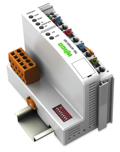
WAGO 750-837/020-000
750-837/020-000 WAGO 750-837/020-000
OutOfStock

CANopen CONTR.256/192KB PGM/RAM
Got questions?
Send us a message
or call us at 1-800-335-5111 for additional assistance.
CANopen CONTR.256/192KB PGM/RAM
Features
- Decentralized control to optimize support for a PLC or PC
- Devide complex applications into individually testable units
- Programmable fault response in the event of fieldbus failure
- Signal pre-processing reduces fieldbus transmissions
- Directly control peripheral equipment for faster system response times
- Stand-alone, compact controller
Approvals
- Bureau Veritas S.A., BV, 13453/DO BV
- TUEV Nord Cert GmbH, IECEx, IECEx TUN 09.0001 X, IEC 60079-0
- Polski Rejestr Statków, PRS, TE/2236/880590/19
- UL International Netherlands B.V., UL, E175199 Sec.1, UL 508
- TUEV Nord Cert GmbH, TUEV Nord, TÜV 07 ATEX 554086 X en., EN 60079-0
- Underwriters Laboratories Inc., UL, E198726 Sec.1, UL 121201
- Korean Register of Shipping, KR, KR HMB05880-AC001
- Det Norske Veritas, Germanischer Lloyd, DNV GL, TAA0000194
- American Bureau of Shipping, ABS, 19-HG1821926
- Brjansker Zertifizierungsstelle, EAC, EAC RU C-DE.AM02.B.00163/19, TP TC 012/2011
- CQST/CNEx, CCCEx, 2020312310000215, CNCA-C23-01
- Nippon Kaiji Kyokai, NK, TA17255M
- RINA Germany GmbH, RINA, ELE066419XG
Specifications
Notes
- Note: Note: Configuration files required (EDS)!The EDS files can be downloaded for free at www.wago.com.
Technical Data
- Communication: CANopen
- Visualization: Without
- CPU: 16 bits
- Programming languages per IEC 61131-3: Instruction List (IL) || Ladder Diagram (LD) || Function Block Diagram (FBD), Continuous Function Chart (CFC) || Structured Text (ST) || Sequential Function Chart (SFC)
- Programming environment: WAGO-I/O-PRO V2.3 (based on CODESYS V2.3)
- Configuration options: EDS device description file || WAGO-I/O-CHECK
- Cycle time: < 3 ms for 1000 bit instructions/ 256 digital I/O
- Baud rate: 10 kBd … 1 MBd
- Bus segment length (max.): 1000 m
- Transmission medium (communication/fieldbus): Shielded Cu cable 3 x 0.25 mm²
- Number of fieldbus nodes on master (max.): 110
- Program memory: 256 kByte
- Data memory: 192 kByte
- Non-volatile software memory: 8 kB
- Memory for fieldbus input variables (max.): 512 Byte
- Memory for fieldbus output variables (max.): 512 Byte
- Number of modules per node (max.): 64
- Number of PDOs: 32 Tx / 32 Rx
- Number of SDOs: 2 SDO servers / 16 SDO clients
- Input and output (fieldbus) process image (max.): 512 Byte/512 Byte
- Other CANopen features: NMT slave || Minimum boot-up || Variable PDO mapping || Emergency message || Life guarding/heartbeat || Empty module configuration
- COB ID distribution: SDO, standard
- Node ID distribution: DIP switch
- Supported profiles: Communication profile: DS-301 V4.01; device profile: DS-401 V2.0; limit monitoring, flank-triggered PDOs, configurable response in the event of an error, DSP 405, NMT master programmable using function blocks
- Indicators: LED (STOP) red: Device/node Stop; LED (RUN) green: Initialization; LED (TX, RX OVERFLOW) red: CAN send/receive buffer overflow; LED (I/O, USR) red/green/orange: Local status, status programmable by user; LED (A, B) green: System power supply status, field supply
- Supply voltage (system): 24 VDC (-25 … +30 %); via pluggable connector (CAGE CLAMP® connection)
- Input current (typ.) at nominal load (24 V): 500 mA
- Power supply efficiency (typ.) at nominal load (24 V): 87 %
- Power consumption (5 V system supply): 350 mA
- Total current (system supply): 1650 mA
- Supply voltage (field): 24 VDC (-25 … +30 %); via power jumper contacts
- Current carrying capacity (power jumper contacts): 10 A
- Number of outgoing power jumper contacts: 3
- Isolation: 500 V system/field
Connection Data
- Connection technology: communication/fieldbus: CANopen: 1 x Male connector; 5-pole
- Connection technology: system supply: 2 x CAGE CLAMP®
- Connection technology: field supply: 6 x CAGE CLAMP®
- Connection type (1): System/field supply
- Solid conductor: 0.08 … 2.5 mm² / 28 … 14 AWG
- Fine-stranded conductor: 0.08 … 2.5 mm² / 28 … 14 AWG
- Strip length: 8 … 9 mm / 0.31 … 0.35 inch
- Connection technology: device configuration: 1 x Male connector; 4-pole
Physical Data
- Width: 50.5 mm / 1.988 inch
- Height: 71.1 mm / 2.799 inch
- Height from upper-edge of DIN-rail: 63.9 mm / 2.516 inch
- Depth: 100 mm / 3.937 inch
Mechanical Data
- Weight: 181.402 g
- Color: Light gray
- Housing material: Polycarbonate; polyamide 6.6
- Conformity marking: CE
Environmental Requirements
- Surrounding air temperature (operation): 0 … 55 °C
- Surrounding air temperature (storage): -40 … 85 °C
- Protection type: IP20
- Pollution degree (5): 2 per IEC 61131-2
- Operating altitude: Without temperature derating: 0 … 2000 m; with temperature derating: 2000 … 5000 m (0.5 K/100 m); 5000 m (max.)
- Relative humidity (without condensation): 95 %
- Mounting position: Any
- Mounting type: DIN-35 rail
- Vibration resistance: 4g per IEC 60068-2-6
- Shock resistance: 15g per IEC 60068-2-27
- EMC immunity to interference: Per EN 61000-6-2, marine applications
- EMC emission of interference: Per EN 61000-6-4, marine applications
- Exposure to pollutants: Per IEC 60068-2-42 and IEC 60068-2-43
- Fire load: 3.041 MJ
- Permissible H2S contaminant concentration at a relative humidity 75 %: 10 ppm
- Permissible SO2 contaminant concentration at a relative humidity 75 %: 25 ppm
Commercial Data
- Packaging type: Box
- Country of origin Sales Organisation Germany: DE
- GTIN: 4045454527129
- Customs tariff number Sales Organisation Germany: 85371091990


