Cart is empty
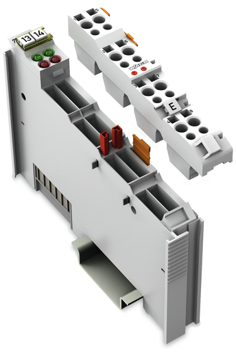
WAGO 753-421
753-421 WAGO 753-421
OutOfStock

2DI
Got questions?
Send us a message
or call us at 1-800-335-5111 for additional assistance.
2DI
Features
Approvals
- Brjansker Zertifizierungsstelle, EAC, EAC RU C-DE.AM02.B.00163/19, TP TC 012/2011
- CQST/CNEx, CCCEx, 2020312310000215, CNCA-C23-01
- TUEV Nord Cert GmbH, TUEV Nord, TÜV 07 ATEX 554086 X en., EN 60079-0
- Bureau Veritas S.A., BV, 13453/DO BV
- UL International Netherlands B.V., UL, E175199 Sec.1, UL 508
- Underwriters Laboratories Inc., UL, E198726 Sec.1, UL 121201
- Polski Rejestr Statków, PRS, TE/2236/880590/19
- Korean Register of Shipping, KR, KR HMB05880-AC001
- Det Norske Veritas, Germanischer Lloyd, DNV GL, TAA0000194
- TUEV Nord Cert GmbH, IECEx, IECEx TUN 09.0001 X, IEC 60079-0
- American Bureau of Shipping, ABS, 19-HG1821926
- National Radio Research Agency, KC, MSIP-REM-W43-DIM750, Article 58-2, Clause 3
- Lloyds Register EMEA, LR, 02/20026 (E6)
- RINA Germany GmbH, RINA, ELE066419XG
Specifications
Notes
- Note: Pluggable connectors and coding fingers (753 Series) are not included.
Technical Data
- Number of digital inputs: 2
- Total number of channels (module): 2
- Signal type: Voltage
- Voltage signal type: 24 VDC
- Supply voltage (sensor): 24 VDC; Short-circuit-protected, isolated channels A short circuit to ground is indicated as an error/fieldbus failure and a message is sent to the supervisory control. The error is canceled automatically after it has been rectified.
- Sensor connection: 2 x (2-wire, 3-wire)
- Input characteristic: High-side switching
- Input filter (digital): 3 ms
- Input current per channel for signal (1) (typ.): 3.7 mA
- Output current per channel: 0.5 A
- Short-circuit current: 1.5 A, pulsating due to thermal overload protection
- Voltage range for signal (0): −3 … +5 VDC
- Voltage range for signal (1): 15 … 30 VDC
- Diagnostics: Short circuit, automatic acknowledgment after error rectified
- Input data width (internal) (max.): 4 bits
- Supply voltage (system): 5 VDC; via data contacts
- Power consumption (5 V system supply): 12 mA
- Supply voltage (field): 24 VDC (-25 … +30 %); via power jumper contacts (power supply via blade contact; transmission via spring contact)
- Isolation: 500 V system/field
- Indicators: LED (A, C) green: Status DI 1, DI 2; LED (B, D) red: Error DI 1, DI 2
- Number of incoming power jumper contacts: 2
- Number of outgoing power jumper contacts: 2
- Current carrying capacity (power jumper contacts): 10 A
Connection Data
- Connection technology: inputs/outputs: 8 x CAGE CLAMP®
- Connection type (1): Inputs/outputs
- Solid conductor: 0.08 … 2.5 mm² / 28 … 14 AWG
- Fine-stranded conductor: 0.08 … 2.5 mm² / 28 … 14 AWG
- Strip length: 9 … 10 mm / 0.35 … 0.39 inch
Physical Data
- Width: 12 mm / 0.472 inch
- Height: 100 mm / 3.937 inch
- Depth: 69.8 mm / 2.748 inch
- Depth from upper edge of DIN-rail: 62.6 mm / 2.465 inch
Mechanical Data
- Mounting type: DIN-35 rail
- Wiring interface: Pluggable
Material Data
- Color: Light gray
- Housing material: Polycarbonate; polyamide 6.6
- Fire load: 1.041 MJ
- Weight: 41.000 g
- Conformity marking: CE
Environmental Requirements
- Surrounding air temperature (operation): 0 … 55 °C
- Surrounding air temperature (storage): -40 … 85 °C
- Protection type: IP20
- Pollution degree (5): 2 per IEC 61131-2
- Operating altitude: 0 … 2000 m
- Mounting position: Horizontal (standing/lying); vertical
- Relative humidity (without condensation): 95 %
- Vibration resistance: 4g per IEC 60068-2-6
- Shock resistance: 15g per IEC 60068-2-27
- EMC immunity to interference: Per EN 61000-6-2, marine applications
- EMC emission of interference: Per EN 61000-6-4, marine applications
- Exposure to pollutants: Per IEC 60068-2-42 and IEC 60068-2-43
- Permissible H2S contaminant concentration at a relative humidity 75 %: 10 ppm
- Permissible SO2 contaminant concentration at a relative humidity 75 %: 25 ppm
Commercial Data
- Packaging type: Box
- Country of origin Sales Organisation Germany: DE
- GTIN: 4044918937368
- Customs tariff number Sales Organisation Germany: 85389099990


